The process of the single-pass color printing cartridge is when the paper is rolled one time by each color cartridge, and these color cartridges are lined up in a row. Unlike the carousel system, this system is much faster and more precise. Usually this system is used in expensive devices.
It is better to describe the process in a step-by-step manner. The first step of the process is the stage of primary exposure. The light from the LED for primary exposure, which is installed inside of the cartridge, reaches the drum. This will remove any charges from the surface of the drum, and ensure that the density of the charge is consistent.
The second step is placing the uniform negative DC bias voltage on the surface of the OPC drum by the PCR (primary charging roller). Intensity setting on the printer is controlling the amount of placed voltage.
The third step is when the “scanner” or the rotating mirror is being fired by a laser beam. And then the beam is reflecting on a set of lenses, while the mirror rotates. Then the beam hits the surface of the drum and leaves the electrostatic image on it. Places that the beam did not hit will remain negatively charged. Each color cartridge is supplied with personal scanner and laser units.
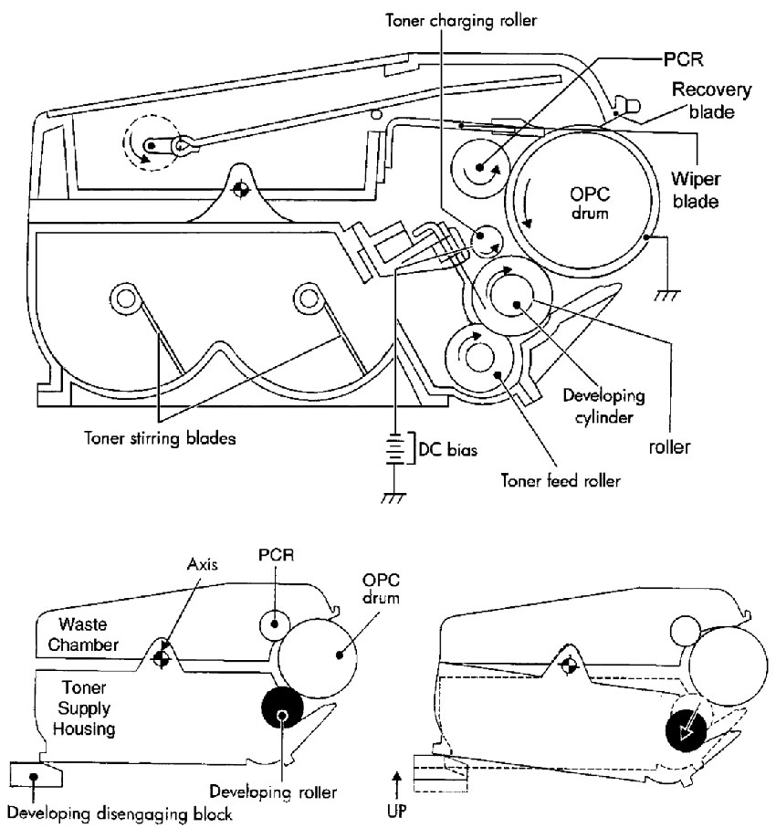
The fourth step, that is called the developing stage, is when your image is being developed on the surface of the drum by the supply chamber (developing section), where the toner particles are stored. There are actually two sub stages in the developing stage: charging of the toner and the development itself. When the toner is being charged the toner stirring blade is turning inside the reservoir. While it is turning, friction helps the negative voltage to build up on the toner. Plus, the negative voltage is also placed on the toner by the toner charging roller. Both charges ensure that the charge placed on the toner is uniform. As soon as the toner is properly charged, the developing roller will be coated with it. Also, the toner is held on the surface by another DC negative voltage. You control this DC bias voltage by the printer intensity setting, and this voltage is controlling the amount of attracted toner. The print density is increased or decreased after that. First, the feed mechanism feeds toner to the developing roller. Usually this feed mechanism is an open-cell foam roller. There’s a metal doctor blade to control the amount of the toner that is on the surface of the developer roller, and to keep the certain amount permanently, it uses pressure. And when the laser exposed areas of the drum reach the developer roller, particles of the toner are attracted to the surface of the drum because the toner is charged with the opposite voltage potentials in contrast with laser exposed surface.
The fifth step is called transfer block. And that’s the main difference between single-pass color printers and monochrome ones. First thing in transfer block is when the attaching roller positively charges the paper. This roller is installed right next to the paper rick-up roller. Also, the attaching roller is pressing the paper against the ETB (electrostatic transfer belt). A positive DC voltage is placed on this transfer charging roller. It is located on the opposite side of the OPC drum, on the back side of the ETB. Each cartridge has its own transfer charging roller. When the ETB is passing charging roller, it picks up the positive charge and draws the toner, which is negatively charged, right onto the paper sheet. Each color cartridge is repeating the same process one more time. When the toner reaches the paper, the positive charge becomes weaker and weaker with each run under each color cartridge. And because of that, transfer charging roller has an increased charge for each color. The paper then peels off the ETB when the belt is at the end of the printing path. After that the belt turns back and is ready to start the process again.
The sixth stage is when the fuser assembly fuses image on to the surface of the paper. The fuser assembly is comprised of the two halves, the lower and the upper fuser rollers. The paper sheet is then passed through the soft rubber roller that presses the paper up to the upper heated roller, which melts the toner into the paper sheet. Upper heater is a flexible sleeve with a heating coil inside. This kind of a fuser allows instant-on fusing, and requires less power.
The last stage is the cleaning of the drum and the belt.
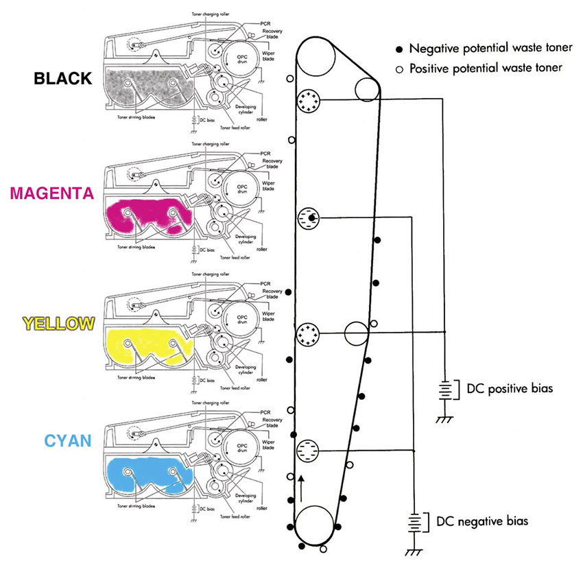
CLEANING THE ETB
The belt is cleaned each time you turn your printer on, when you have your printer’s covers closed, when starting a printing, when you’ve printed a certain number of pages. Both negative, as well as positive bias voltages are applied to the transfer charge rollers. These voltages help to remove any residual toner from the ETB surface, and transfer it to the OPC drum, where the wiper blade will clean it off. When you’re done printing there are toner leftovers on the ETB, both positively and negatively charged particles. And that is why we need both kinds of voltages. Because the developer roller always contacts the drum, you need to always make sure that there’s no old toner left in supply chamber. During the cleaning process, you need to be careful, so your developer roller and the drum won’t be in contact. To make this task easier, the bottom half of the cartridge is able to pivot, and that will move the developer roller away from the drum. There’s a small block under each cartridge. That block is pushing up to disengage the roller.
CLEANING THE OPC DRUM
After the image is already being transferred to the paper with the wiper blade, the drum is cleaned. There’s nothing new in this process: the wiper blade cleans off the toner from the surface of the drum, and then the cleaned off toner is guided to the waste reservoir by the recovery blade. Then the wasted toner is pressed against the back wall of the reservoir by the waste toner plate. The only difference here is that, the other rollers need to be cleaned too. In usual printing process, the toner sticks only to the primary charging roller and the toner charging roller. Different values of the DC bias voltage are applied to both rollers, so the toner is transferred onto the drum, where the wiper blade will clean it off. Toner charging roller and the primary charging roller are cleaned each time you turn on the device, your printer’s covers are closed, you start a new printing cycle, and you’ve printed a certain amount of pages.
CALIBRATION OF YOUR PRINTER
Before anything starts there’s a cycle of calibration. Each time you turn the printer on, or when you install a new toner cartridge, or at specific page intervals, or when the printer has reached 8 run-time hours, printer will calibrate itself. To calibrate itself, the device is printing solid blocks and halftones of each color. And when these printed pieces reach the top of the belt, there’s a sensor to detect them, to calculate the density, and adjust printer settings as needed.
COMPONENTS OF THE NON-MAGNETIC COLOR TONER CARTRIDGE
Non-magnetic color toner. This toner is used in new generation of HP color systems. These color toners are chemically grown, polymerized toners. Unlike the usual pulverized ones. Because of the extremely round particles, polymerized toners cause less wear, and allow you to calibrate the color more accurately. These toners use almost no powdered iron. Some have no iron at all.
Developer roller. This roller is basically a metal shaft with rubber wrapped around it. On the outside it has conductive sleeve. Printer’s high-voltage power supply sends electrical signals to attract the toner to the roller. There’s nothing like magnets or anything inside, the toner is attracted only by those impulses.
Toner charge roller. This roller imparts a charge into the toner while the feed roller is feeding the toner to the developing roller. This extra charge makes the charge on the developing roller more uniform, and that gives more accurate color on your prints.
Doctor blade. This part is controlling the amount of toner that is on the surface of the magnetic roller, when it presses the silicon rubber blade against the sleeve of the magnetic roller, the toner leftovers come off. Also, this helps to keep the toner statically charged, so it spreads evenly on the sleeve of the magnetic roller. There’s a metal doctor blade in the most part of color toner cartridges.
PCR. There are two main functions the primary charge roller has. First, it is applying a DC signal to the drum’s surface, so the printer laser is able to print on the surface. Second, it is applying an AC signal to the drum after printing, so any residual charges that were left on the surface of the drum are removed.
Drum. Those drum which are used in disposable cartridges are called organic photoconductors (OPC). This notion refers to the type of chemicals which were used for aluminum tube coating, the base of the drum. All drums are sensitive to light. Usually there are three layers of coating on the drum. The first layer is insulator, the second layer is reactive, it reacts to the light, and the last one is a protective layer. For how long your drum will last, depends on this last, protective, layer.
Wiper blade. There’s a rubber edge on the wiper blade that cleans all of the toner that did not reach the paper. This blade slides right on the drum surface, so it is one of the main reasons of the drum wear.
Recovery blade. This blade is made from mylar and is very thin, it guides the wiped off toner to the chamber for wasted toner. Should there be no recovery blade, or maybe it is damaged, the toner would spill right on the printed pages.
Waste chamber. It is the place where all of the wasted toner is stored. This part of the cartridge usually contains the drum, charging roller, recovery and wiper blades. In the HP 4600 there’s also a bar for the primary exposure LED.
Supply chamber. It is the place for the new toner that is not yet used. This part of the cartridge contains the doctor blade and the magnetic roller assembly.
Adapted from http://www.uninetimaging.com/