Until very recently there were no reasons for downgrading Samsung ML-2160 firmware. To get rid from the chip you need to find the fix firmware, due to which the device would stop monitoring the chip what gives you an opportunity to stop paying for chips and refill cartridges for free. When Samsung released new ML-2160 V1.01.02.00 firmware, the situation changed rapidly. Samsung have decided to stop fooling around and began to sign new firmware versions with electronic digital signature (EDS), meaning not being able to install modified firmware without having the original Samsung EDS. It is impossible to pick or hack EDS, unless there’s a leak of EDS or should anyone find a weak spot in mechanization of the testing algorithm.
The firmware is signed with EDS using the secret (private) key, only Samsung has one. When being upgraded, the printer identifies the firmware with its own key that’s inside of the devise. These keys are different, asymmetric encryption algorithms are used. Having an open key it is impossible to get the closed one and upgrade the firmware, sign it and install it back to the printer. The signature is based on ECDSA, it is 512 bits, which means that it has to raise 2 to the power of 512, which is a lot and impossible.
But there’s another way, simpler. Using JTAG adapter you can connect to the processor, upload a boot of the previous firmware version without the EDC. Then, boot with no-EDC firmware version and install fix firmware.
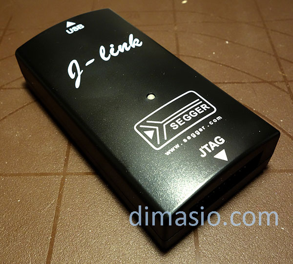
Let’s get started. To fulfill our task we need the JTAG adapter. You can buy it at www.segger.com. Also, here you can find and download required drivers and upgrade your adapter’s firmware to the latest version. Also, there’s a more acceptable in terms of price option – you may go to aliexpress.com, but it is all about your personal preferences.
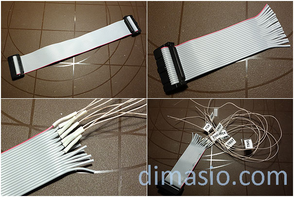
Adapter comes with a loop that needs to be prepared for the further process. Cut the loop in two, one half stays until you need it, the other is going to be processed. You need to clean up required wires, according to the pinout on the picture.
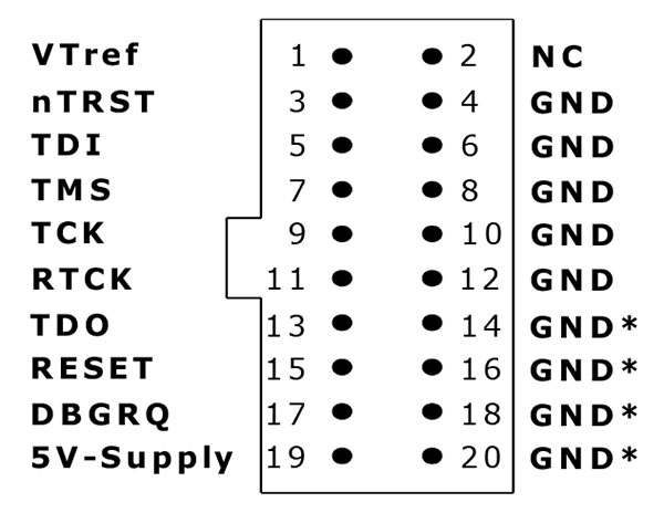
We need following pins VTref, nTRST, TDI, TMS, TCK, TDO, 5V-Supply, Gnd. Next, solder it with hookup wires for more convenient connection with the formatter and label them not to get your “wires crossed”.
After the loop is done, you need to test the charging, +5 volts to the 19th output of the loop. Switch the tester to the DC voltage mode and connect it between the 4th and 19th output. Turn on the commander. Say “power on” (without brackets). If you see 5 volts, that’s great. Say “power off” and 5 volts should be gone. If when powering the JTAG (commander) there’s 5 volts already on the 19th output, you need to say “power off perm”, so you will have 5 volts disabled when it starts. Now when you connect the JTAG to the computer there will be no charge on the 19th output.
Next, disassemble your printer and take the formatter board. Using JTAG output pinout and following photos solder corresponding outputs.
Let’s start with front side of the board. Connect outputs 1 (VTref), 19 (5V-Supply), and 4 (Gnd) according to the left side of the picture. Connect output 7 (TMS) to the processor pin 66, previously unsoldered from the board. Attention! The pin is very fragile you can easily tear it off. I was using slim tweezers and a soldering iron here. Hold a pin firmly with tweezers heat it with the iron and slowly lift it up. Next, solder a wire to it. You need to tape the wire to the board so the processor pin will stay in place while you’re ma the board. It is better to use bare varnished wire, it is more flexible, and you will prolong the output’s life. After your firmware is downgraded, you may not solder the output back to the board, everything will work just fine.
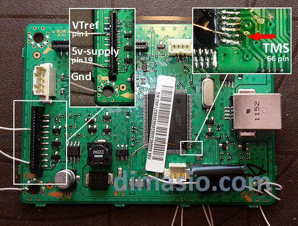
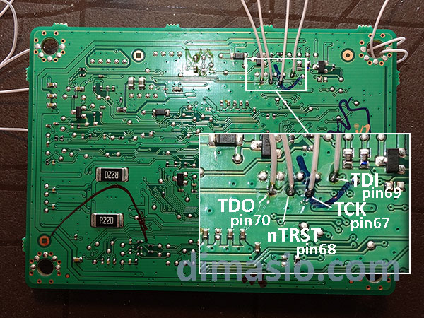
Now, the back side of the board. Solder the rest outputs of the loop according to the image and pinout of the JTAG adapter. TDO (output 13), TDI (output 5), TCK (output 9), nTRST (output 3).
Run the J-link commander. Enter commands without brackets. Approve the entry by pressing “Enter”.
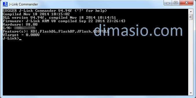
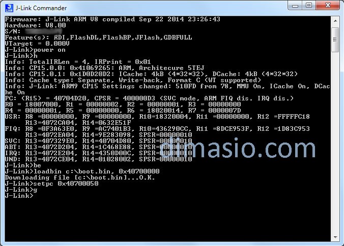
Type in “power on”. Quickly type in “h” command. If you’ve done everything correctly you should see occupied processor data in the commander window.
Then type in “be”.
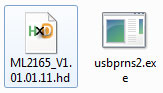
Download boot.bin loader and save it in the root directory of disc c:\
Type in ”loadbin c:\boot.bin, 0x40700000”.
Wait a moment for your file to download. If everything went successfully you’ll be notified by “O.K.” in command line.
Type in “setpc 0x40700050”.
And then “g”.
After a few seconds the printer (formatter board) will run in boot mode. You know it started when you hear gurgling that occurs when new USB device is recognized by the system.
As usual, drag the original firmware into the loader usbprns2.exe. You will see running points on the screen, and then the window will close. After a little while the printer will restart. The firmware is now downgraded.
That’s it, the device now has the firmware without EDC. Now you may buy the fix firmware at your dealer’s store and simply install it in your device.