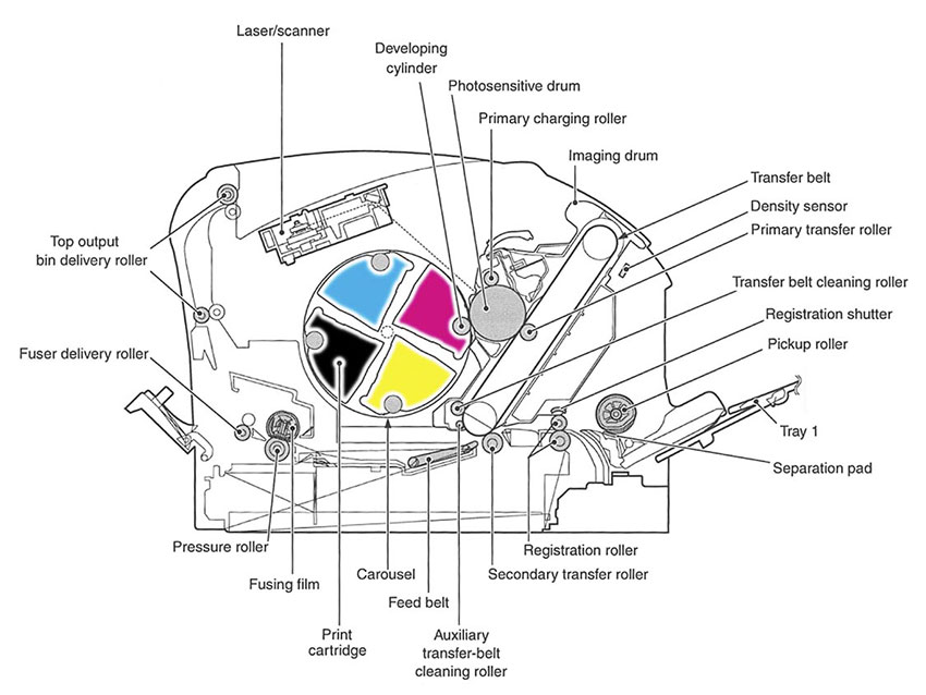
The carousel color type is another type of the printing engine, which is different from the single-pass type. Single-pass systems are more expensive to produce than the carousel system. And they are. Since there’s a separate laser scanner in the single-pass systems and each individual cartridge has all the associated security. And there’s only one for each cartridge in the carousel system. Maybe it is not as complicated as a single-pass system, but the process still includes quite a few interesting things to look at. All cartridges, and there are four of them, are being held by the carousel. It rotates depending on which cartridge is needed at the moment. While the technology is developing, this kind of a system is usually used in cheaper printers. For example, HP CLJ 1500 and 2500 are pretty similar to the HP CLJ 4500, but the first ones are more advanced.
The printing process of the non-magnetic cartridge is best shown step by step. First, the PCR places a negative DC voltage on the surface of the OPC drum. Printer’s intensity setting then allows you to control the amount of the placed voltage.
The second step, the imaging section, is when the “scanner” or the rotating mirror is being fired by a laser beam. And then the beam is reflecting on a set of lenses, while the mirror rotates. And then the beam hits the surface of the drum and leaves the electrostatic image on it. Those areas which were not impacted by the laser will have the negative charge retained.
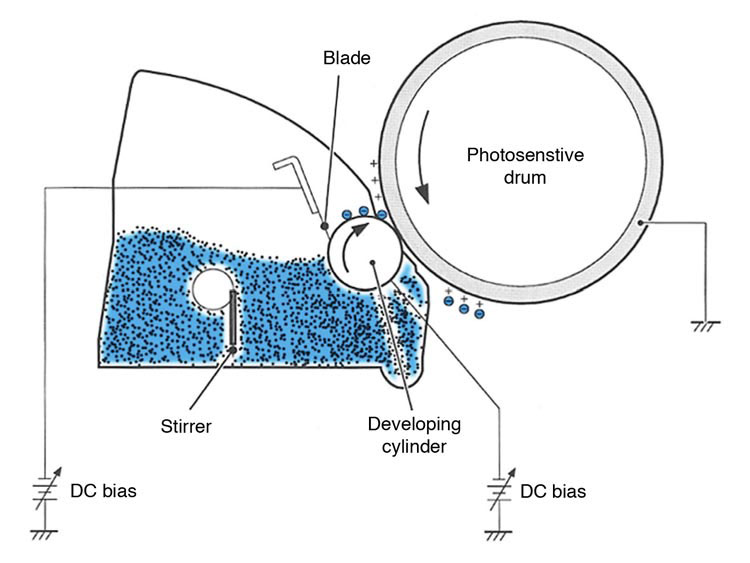
The third step, the developing stage, is when your image is being developed on the surface of the drum by the supply chamber (developing section), where the toner particles are stored. When the stirring blade turns into the hopper the toner is then pushed onto the developer roller. There’s a negative potential building up on the toner, because of the friction. Now the toner is starting to stick to the developing roller. At that time, the developer roller is being powered by the negative DC bias voltage. You control this DC bias voltage by the printer intensity setting, and this voltage is controlling the amount of attracted toner. The print density is increased or decreased after that. There’s a metal doctor blade to control the amount of the toner that is on the surface of the developer roller, and to keep the certain amount permanently, it uses pressure along with the second DC bias voltage. And when the laser exposed areas of the drum reach the developer roller, particles of the toner are attracted to the surface of the drum because the toner is charged with the opposite voltage potentials in contrast with laser exposed surface.
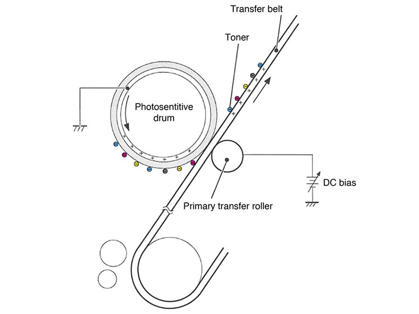
The fourth step is the primary transfer. And this is the main difference between the HP CLJ 2500 and HP 4600, or monochrome printing process. The first thing here is transfer roller placing the positive charge on the back of the transfer belt. After what, the toner that is negatively charged is going to the transfer belt that is positively charged. For each color needed the process is repeated again. The voltage is increased for each new color, and that helps the toner to stay in the right place on the surface of the belt.
Fifth – the secondary transfer. When the paper is on the transfer belt the secondary transfer roller passes by. And when it passes by, it leaves a positive charge on the paper, and that attracts the toner from the belt to the paper. When this stage is done, the secondary transfer roller is powered by another DC dias, so the toner won’t stick to it. The paper then peels off the transfer belt because of the paper stiffness and the eliminator of the static charge.
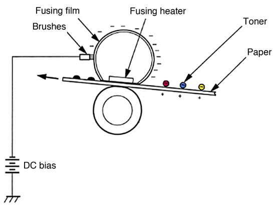
The sixth step is when the fuser assembly fuses image on to the surface of the paper. The fuser assembly is comprised of the two halves, the lower and the upper fuser rollers. The paper sheet is then passed through the soft rubber roller that presses the paper up to the upper heated roller, which melts the toner into the paper sheet. Upper heater is a flexible sleeve with a heating coil inside. This kind of a fuser allows instant-on fusing, and requires less power. There’s also a DC bias voltage placed on the sleeve, which allows holding the toner to the paper firmly, so it is not scattering.
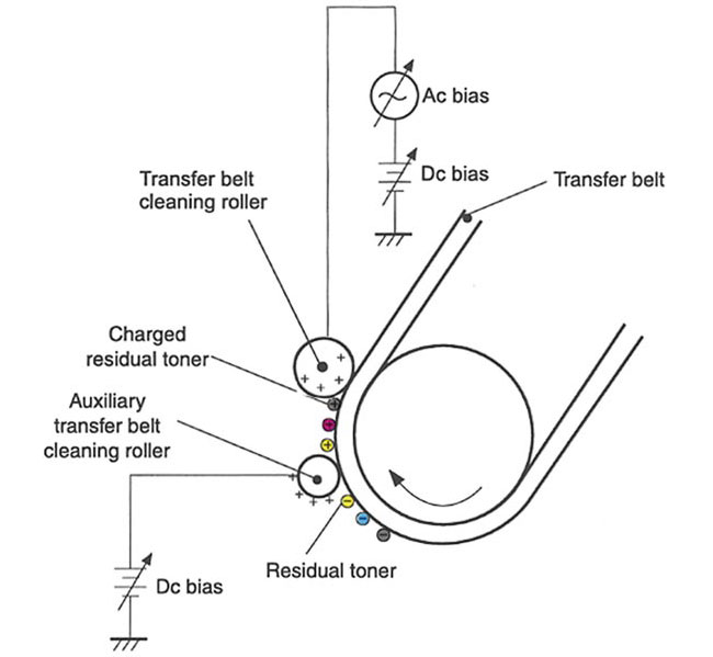
The seventh step is cleaning the transfer belt. The belt is cleaned each time you turn your printer on, when you have your printer’s covers closed, when starting a printing, when you’ve printed a certain number of pages. A positive DC bias voltage is placed on the transfer belt cleaning roller. And that helps the toner to stick to the belt and not fall inside of the printer. Next, placing the DC bias on the cleaning roller. And this charge is stronger than the one previously applied by the auxiliary roller. Previously positive charge now becomes negative. The difference between the drum and the belt is produced by placing another DC bias on the transfer belt. The cleaning roller of the OPC drum gets another DC bias. And that causes the residual toner to transfer onto the drum.
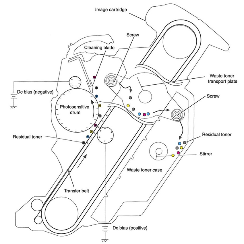
The last step is the cleaning of the drum. The drum is cleaned by the wiper blade each time the process described above ended. There’s nothing new in this process: the wiper blade cleans off the toner from the surface of the drum, and then the cleaned off toner is guided to the waste reservoir by the recovery blade. What’s different here is the movement of the toner and the waste toner case. Then the auger picks up the waste toner from the drum unit. The toner is then delivered to another auger and after that is moved to the waste toner case. This case is a compartment of the transfer belt.
Now you see that DC power supply has lot things to do during the process. So, even the small deviation in power supply may cause serious problems.
CALIBRATION OF YOUR PRINTER
Before anything starts there’s a cycle of calibration. Each time you turn the printer on, or when you install a new toner cartridge, or at specific page intervals, or when the printer has reached 8 run-time hours, printer will calibrate itself. To calibrate itself, the device is printing solid blocks and halftones of each color. And when these printed pieces reach the top of the belt, there’s a sensor to detect them, to calculate the density, and adjust printer settings as needed.
RESET CHIPS
Reset chips are working in the same way that all other HP chips do. These chips are controlling notification messages TONER LOW, TONER OUT or REPLACE CARTRIDGE. There’s a separate chip for each individual cartridge. It is unnecessary to replace the chip for the cartridge to work. But should you not, you will have no notifications about the toner left. When you have your chip utilized, you need to clear it by pressing the CANCEL button. After that you will see the “NON-HP PRINT CARTRIDGE” message. You’ll see it only once. There will be no information about the cartridge on the SUPPLIES STATUS page.
COMPONENTS OF THE NON-MAGNETIC CAROUSEL COLOR TONER
Non-magnetic color toner. This toner is used in new generation of HP color systems. These color toners are chemically grown, polymerized toners. Unlike the usual pulverized ones. Because of the extremely round particles, polymerized toners cause less wear, and allow you to calibrate the color more accurately. These toners use almost no powdered iron. Some have no iron at all.
Developer roller. This roller is basically a metal shaft with rubber wrapped around it. On the outside it has conductive sleeve. Printer’s high-voltage power supply sends electrical signals to attract the toner to the roller. There’s nothing like magnets or anything inside, the toner is attracted only by those impulses.
Toner charge roller. This roller imparts a charge into the toner while the feed roller is feeding the toner to the developing roller. This extra charge makes the charge on the developing roller more uniform, and that gives more accurate color on your prints.
Doctor blade. This part is controlling the amount of toner that is on the surface of the magnetic roller, when it presses the silicon rubber blade against the sleeve of the magnetic roller, the toner leftovers come off. Also, this helps to keep the toner statically charged, so it spreads evenly on the sleeve of the magnetic roller. There’s a metal doctor blade in the most part of color toner cartridges.
PCR. There are two main functions the primary charge roller has. First, it is applying a DC signal to the drum’s surface, so the printer laser is able to print on the surface. Second, it is applying an AC signal to the drum after printing, so any residual charges that were left on the surface of the drum are removed.
Drum. Those drum which are used in disposable cartridges are called organic photoconductors (OPC). This notion refers to the type of chemicals which were used for aluminum tube coating, the base of the drum. All drums are sensitive to light. Usually there are three layers of coating on the drum. The first layer is insulator, the second layer is reactive, it reacts to the light, and the last one is a protective layer. For how long your drum will last, depends on this last, protective, layer.
Wiper blade. There’s a rubber edge on the wiper blade that cleans all of the toner that did not reach the paper. This blade slides right on the drum surface, so it is one of the main reasons of the drum wear.
Recovery blade. This blade is made from mylar and is very thin, it guides the wiped off toner to the chamber for wasted toner. Should there be no recovery blade, or maybe it is damaged, the toner would spill right on the printed pages.
Waste chamber. It is the place where all of the wasted toner is stored. This part of the cartridge usually contains the drum, charging roller, recovery and wiper blades. In the HP 4600 there’s also a bar for the primary exposure LED.
Supply chamber. It is the place for the new toner that is not yet used. This part of the cartridge contains the doctor blade and the magnetic roller assembly.
Adapted from http://www.uninetimaging.com/