There are special sensors installed in copying machines, faxes and other printing devices for paper registration purposes. These sensors are checking the tray for the paper supply, according to the paper supply in the paper path. Depending on information received from the registration sensor, processor reforms different actions.
Usually, the paper sensor consists of mechanical and electrical parts.
Mechanical part is a simple plastic flag, which uptilts when contacts the paper.
Electrical part may be represented by contact group or optical coupler.
Contact group is a simple switcher, which locks or breaks the contact when the plastic flag uptilts. This kind of the sensor is not good, because after a while, the contacts start to oxidize and it’s not switching each time.
Optical coupler is a device that uses the IR LED as an oscillator, and, for example, a phototransistor, photodiode or photothyristor as a photodetector of a signal from the LED. In this case the paper sensor flag closes or opens the light flux for the LED, thereby impacting the photodetector. This picture will show you the look of the electrical circuit of the optical coupler.
It runs like this: the LED is permanently radiates, the flag locks or breaks the light flux that falls on the photodetector, and on the output we have “nil” with the locked flag, and the “one” with the opened. Further process is usually carried by the processor of the device.
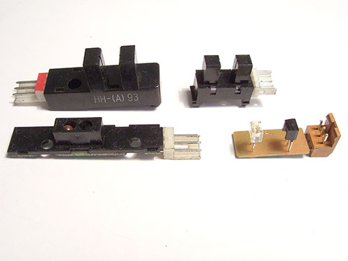
Also, there are other paper registration sensors, where the radiating element and photodetector are installed at an angle with each other. When the paper reaches the scope of the sensor, the light beam of the radiator reflects from the paper and reaches the photodetector. This way the device registrates paper. You can see this type of the sensor on the picture at the lower left corner. There are also other optical couplers presented in that picture. They have different design peculiarities, but the work process is all the same.
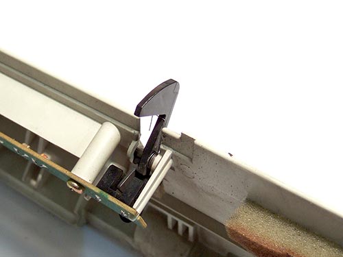
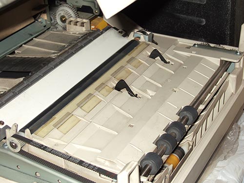
This picture shows paper registration sensors inside of the device.
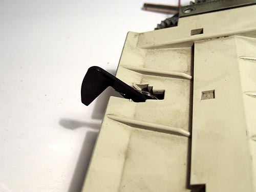
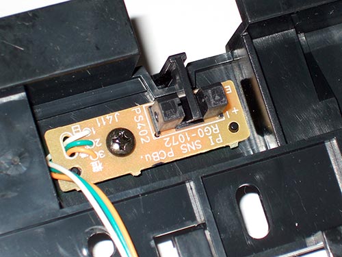
As an example, you can see the lower part of the sensor – the optical coupler. This kind of sensor is installed in HP LJ 1200.
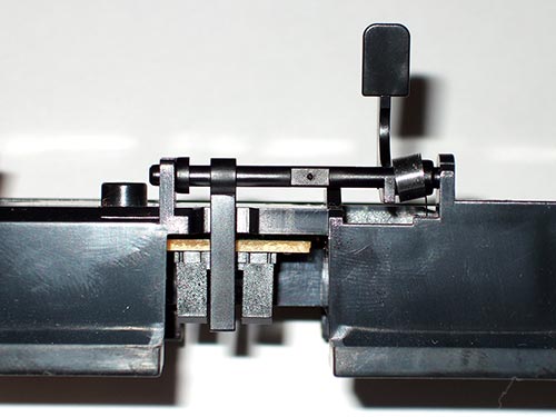
In this picture, you can see the sensor as a whole. You can see both mechanical and electrical part here.
Let’s look at some other paper registration sensor failures.
Sometimes it happens that the sensor flag axis stucks and it doesn’t go back to the primary position. Usually it could be neutralized by cleaning the mechanical part of the sensor. It also happens that the sensor flag, simply grinds down under the influence of sliding paper. That can be fixed by the replacement of the flag. Sometimes (quite rarely) there may be problems with the optical coupler. You can check the performance of the optical coupler this way: using the tester, check the voltage across the radiator (LED) and then, by opening and closing the flag, check the voltage excursion on the output of the optical coupler. Also, you may check the optical coupler using the service menu of your device. One more option, is to turn the flag down and turn the device on. If the optical coupler functions properly, then the device will indicate the error of the sensor. But it’s not always happening this way, it depends on each particular device and on power-on self-test algorithm. But you may use this method to quickly find the malfunction.